Pin Gages vs. Optical Measurement for Small Diameter Tubing
One of the fundamentals of small parts sourcing is that making informed decisions about specifications has a huge impact on optimizing manufacturability. For instance, by taking a part’s end use into consideration, you can determine which tolerances are most critical and will, in turn, drive the production and cost of your parts.
Related article: Your Tight Tolerance Could Be Seriously Affecting Part Cost
There are a lot of factors that can have an effect on whether parts will meet the specified requirements for dimensions and tolerances. In this blog, we look at a factor that may be important in optimizing manufacturability of parts such as small precision tube cutting — namely, the method for determining whether its inside diameter (ID) meets requirements.
How to Measure Tubing ID — and Why It’s Important
Small diameter tubing is widely used in countless applications in a broad range of industries, including (but certainly not limited to):
- Medical devices
- Electronics
- Life sciences
- Physics research
- Aerospace
- Chromatography
- Veterinary medicine
- Automotive
- Chemical processing
For example, cutting metal tubes often referred to as hypodermic tubing can be precision metal cut to length for use in medical devices requiring strength, uniformity, and corrosion resistance. This includes devices for minimally invasive surgical and therapeutic applications such as:
- Catheters
- Endoscopy
- Laparoscopy
- Arthroscopy
- Ophthalmology
- Biopsies
- Dental procedures
- Blood glucose collection
- Orthopedics
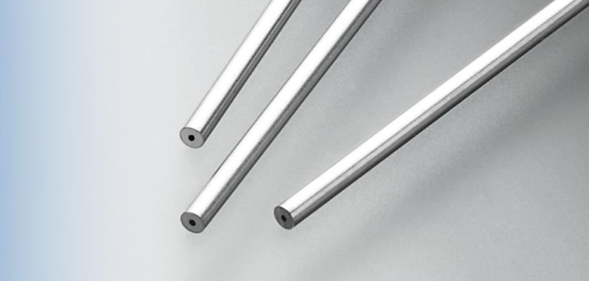
Small precision tube cutting for medical devices is available in different outside diameters (ODs) as well as different IDs and wall thicknesses.
The secret to measuring and verifying the ID of these and other types of small diameter tubing is to agree ahead of time on the tool and method to be used. Consistent inspection can mean the difference between meeting specifications for very precise applications and incurring the cost of additional work.
Let’s look at two common methods of inspecting the ID of small tubing: pin gages and optical measurement.
The Simple Yet Effective Pin Gage
Traditionally, the inside diameter of small diameter tubing or cylinders is measured using pin gages, a simply designed, failsafe method of measurement. Sometimes called attribute or fixed limit gages, pin gages let you inspect a part for conformity and quickly determine whether it is functionally in compliance.
A pin gage is a small pin that is calibrated to be inserted into a part to determine the press fit ID and assure that the diameter is not too small. The process involves using a series of calibrated pins having gradually increasing diameters.
The pins are inserted into the small tubing in size sequence to find the largest pin that fits without stretching the tubing. Depending on the softness of the tubing material, water or a lubricant may be used to prevent the pin from sticking to the tubing ID surface.
For most small diameter tubing sizes with an ID from 0.005” to 0.200”, pin gages yield acceptable results that can be correlated. However, because it is a simple pass-fail method of inspection, pin gages are not designed to provide a measurement value for individual characteristics of the part’s diameter.
Considering Pin Gage Tolerances
It is also important to keep in mind that a pin gage can only measure one limit of tolerance, not both plus and minus. In addition, pin gages come with their own tolerances, which can lead to stacking.
Pin gage tolerance classes are established by the National Institute of Standards and Technology (NIST) and use letter designations such as ZZ, Z, Y, X, XX, and XXX. The difference between the different classes of gages is the tolerance allowed in the manufacturing process of each gage.
In general, the earlier in the alphabet (and the more letters added), the smaller the tolerance allowance. For example, with gages ranging in size from 0.001” to 0.08250”, Class Z gages have a tolerance of no more than 0.0001”, while Class X gages have a tolerance of no more than 0.00004”.
Other Limitations of Pin Gages for Measuring Small Precision Tube Cutting
With very small IDs — say, less than 0.004” — it is challenging to insert a delicate pin gage into a small diameter tube without bending the tube or causing damage to the pin gage. Pin gages themselves are subject to wear and need to be monitored for damage.
In addition, results can vary from user to user and not consistently meet the pass-fail criteria. And for inspecting a very long cylinder, such as small diameter tubing that is as long as 6’ in length and requires a consistent ID throughout, a pin gage is impractical.
A More Sophisticated Option for Inspecting Small Diameter Tubing
For more exacting needs or small parts tubing with IDs that cannot be measured with standard pin gages — for instance, with diameters of 0.002” to 0.004” — optical measurement offers a more sophisticated option for calculating the diameter of a cylinder or tube.
The method can be simple, such as using a light to visually check a tube for blockage or to measure a point just inside the tube’s end. Generally, however, optical measurement uses a sensor to measure various points around the circumference and inside a tube, and then runs the numbers through an algorithm to determine if the average ID is within tolerance.
Optical measurement is more precise than pin gages and can be used to measure circles, arcs, and more complex shapes. It is great for making sure liquid will flow through long, small diameter tubing (again, an application where a pin gage may not be practical).
However, there are drawbacks to optical measurement.
Disadvantages of Optical Measurement vs. Pin Gages
A sensor-based optical measurement system is more costly than using pin gages. Moreover, optics can look only so far into a tube and cannot resolve deep into the Z-axis, where a pin gage can and must pass all the way through.
Although optical measurement may provide assurance that a tube’s average diameter is within specifications, it will not tell you if the ID is consistent throughout the tube. Since the system averages what it “sees,” issues such as a protrusion in the tube might just be averaged in.
However, because a pin gage needs to pass through the smallest point in the ID, the gage might detect a protrusion that an optical system cannot measure.
The optical method also may not be accurate enough if another part needs to fit into the tube, requiring the ID to be double-checked with a pin gage or other Go/No Go method to verify fit.
In addition, optical measurement can be affected by the surface finish and cleanliness of the part measured, as well as the repeatability of part placement in relationship to the optic sensor.
Some General Guidelines for Inspection of Small Parts Tubing
In much the same way you put time and effort into determining part dimensions and tolerances, you should carefully weigh your options when deciding how to determine if the ID of small tubing meets your specifications.
As always, it is important to consider the part’s end use. For example, will the tube need to carry gas or liquid? If so, optical measurement may be the most reliable way to ensure that the tube’s diameter is sufficient to allow gas or liquid to flow.
However, if the tube length is short (say, under 1”), a pin gage may be perfectly acceptable. As long as it is calibrated correctly and does not have any wear or damage, a pin gage will tell you if the short tube’s ID is too small. As an added plus, a pin gage is less expensive than optical measurement.
Some Guidelines for Using Pin Gages
When utilizing pin gages, you should use a master gage that you have calibrated, either internally or externally, and that is NIST traceable.
Additionally, it is important to make sure you and your vendor are using the same quality of calibrated gage. That way you will not incur unnecessary added cost due to false discrepancies in measuring the ID of small diameter tubing.
Deciding which pin gage tolerance class is most appropriate will depend on two things:
- How closely the process is held
- Whether additional tightening of the tolerance boundaries from using a lower-class gage can still achieve the results you need
When in doubt, your manufacturing partner can help you consult the gage maker’s tolerance chart to determine the best pin gage for your needs.
Specify Your Small Precision Tube Cutting ID Inspection Method Up Front
It is also vital to tell your partner, up front, what method you plan to use to inspect your finished parts. Why is this so important?
One Metal Cutting customer provided us with tubing that the supplying vendor had indicated met the customer’s requirements of 0.015” maximum ID. However, when the customer inspected the finished parts, they were rejected because a 0.015” calibrated pin gage would not fit into the tubes.
What was the discrepancy? The customer had not specified that they would be inspecting the parts by using pin gages, and since the parts were destined to carry liquid, the tubing supplier had inspected the tubing using optical measurement.
This is a case where you can clearly see how the method of inspection, not just the specified ID and end functionality, must be taken into consideration. Although the parts were functionally correct, they were rejected for not meeting the customer’s ID inspection requirements.
Bottom line, by keeping the lines of communication open and making sure you and your manufacturing partner are informed, you can work together to meet your small tubing ID goals and pass inspection with flying colors.
For tips on how to improve the accuracy of your specs and project quotes, download our free guide How to Fine-Tune Your Quote Request to Your Maximum Advantage: Frequently Asked Questions in Small Parts Sourcing.


