It’s Round, It’s Straight, It’s 3D!
An important element of optimizing for the manufacturability of small metal parts is the Geometric Dimensioning and Tolerancing (GD&T) standards that are used to communicate how parts should be manufactured.
As part of our continuing exploration of GD&T, here we take a look at cylindricity — a characteristic of geometric tolerancing that may be called out on an engineering drawing to control both the roundness and straightness of a cylindrical part.
What Is GD&T Cylindricity?
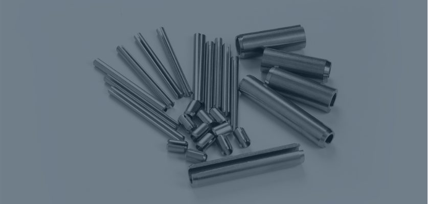
In the most basic terms, GD&T cylindricity is an indicator of roundness along the full length of a part. It is a characteristic that may be indicated in specifications for shafts, pins, and other parts that need to be both round and straight along their axis.
Cylindricity is different from circularity, which is a two-dimensional measurement of roundness at only one point — a cross section — on a cylindrical part. It is also different from concentricity, which compares roundness at two different points or compares an outside diameter and an inside diameter (OD and ID).
Instead, GD&T cylindricity is a three-dimensional feature that applies to the entire surface simultaneously and requires you to consider straightness along the part’s axis as well as the part’s circularity in relation to the axis.
In a perfect world, all the points around the surface of a cylinder would be the same distance from a shared axis. The ideal cylinder would be one that is perfectly round and perfectly straight, with no taper.
What Is Cylindricity Tolerance?
As is true with other GD&T features, the callout on a drawing for a cylindrical part may include a tolerance that defines how much deviation from “perfect” cylindricity is acceptable in the part. The cylindricity tolerance allows for some imperfections while still making sure that the part will function as intended, by limiting taper, out of roundness, and any variation in straightness.
The cylindricity tolerance zone — that is, the area into which all points along the entire length of the cylinder would have to fall — is two concentric (coaxial) cylinders. In other words, the zone is the “space” between two theoretical cylinders sharing the same axis.
The value of the cylindricity tolerance is the radial distance between the two coaxial cylinders. A part’s cylindricity tolerance must be less than its diameter tolerance.
The surface that is being controlled must fall within the cylindricity tolerance zone. If a part is not both sufficiently round and sufficiently straight along its axis, it would not fit into that zone and, therefore, it would not qualify as cylindrical according to the part’s specifications.
How Is GD&T Cylindricity Measured?
To measure cylindricity, a part would be rotated around the spindle of a precision measuring device while a probe is used to record the surface variation along the length of the part. The results are graphed and then checked against the allowable cylindricity tolerance zone.
For instance, a cylindrical part might be placed on a turntable and, as the part is rotated, a height gage or other measuring device is moved up or down the part to measure the surface profile. The profile data would then be analyzed using a polar graph or a computer algorithm to determine if the cylindrical feature is within specifications.
GD&T Cylindricity Tolerance in Rods and Tubes
At Metal Cutting Corporation, we specialize in working with small metal rods and tubes — typically, taking parts that have the same diameter throughout and cutting them to specified lengths. Therefore, the cylindricity tolerance we can hold is subject to whatever tolerance the rod or tube manufacturer can hold.
However, our capabilities also include centerless grinding, which can be used to improve cylindrical characteristics. Therefore, cylindricity may be called out on some machined parts where we can perform additional work that allows us to hold tighter tolerances for overall diameter and cylindricity than what the rod or tube manufacturer can hold.
Where Tightly Held Diameters Help Cylindricity
That being said, we don’t often get callouts for cylindricity at Metal Cutting. Our customers are far more concerned with tight tolerance diameters and characteristics such as parallelism, angles, and burr-free, perpendicular end cuts.
However, if you hold a tight diameter tolerance along the entire length of a rod or tube — as we typically do here at Metal Cutting — chances are good that it will also be suitably cylindrical.
Remember, though, that in addition to measuring a rod or tube diameter at different points along its entire length, it is important to look at the part’s straightness — that is, how the part rotates on its axis at different points — if you want to be absolutely sure it is cylindrical. If the part is not sufficiently cylindrical, it will not rotate on its axis.
For the Best Results, Call It Out!
A true cylindrical part will be both round and straight within the specified tolerance along its entire length. As with other GD&T features, providing Metal Cutting with detailed drawings and complete specifications up front, including callouts for cylindricity and other important characteristics, is crucial to ensuring the best results for your small metal part needs.
In addition to helping us deliver a quality product, these drawings and specifications play a vital role in helping to control costs, reduce waste, and maintain timely and efficient production schedules. In other words, details are vital to optimizing the manufacturability of your product.
For tips on how to maximize the accuracy of your project quotes and optimize part production, download our free guide, How to Fine-Tune Your Quote Request to Your Maximum Advantage: Frequently Asked Questions in Small Parts Sourcing.


