What Is Perpendicularity?
Perpendicularity is one of the GD&T features sometimes indicated on engineering drawings. Represented by an upside-down “T” and called out in inches or in degrees, it generally refers to a GD&T tolerance that controls either:
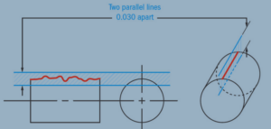
- The perpendicularity between two 90° surfaces or features, with two parallel planes acting as the tolerance zone
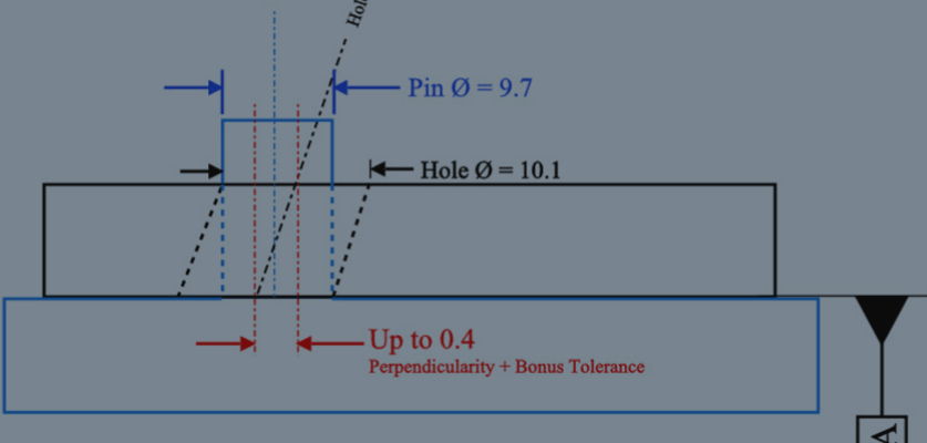
- How perpendicular an axis needs to be to a particular reference point, represented by a cylinder around a theoretical, perfectly parallel axis
However, when we talk about measuring perpendicularity here at Metal Cutting Corporation, we usually mean determining the perpendicularity in terms of the part itself — such as a metal rod, tube, or wire — in relationship to the end cut (or squareness) of that part.
How to Measure Perpendicularity
Measuring the perpendicularity of a surface typically requires the use of a height gage, with either the gage or the part locked to a 90° datum to determine how perpendicular the surface is. The entire surface must be measured to determine if it is within the acceptable perpendicularity tolerance.
Alternatively, calling out the maximum material condition allows the use of a gage to measure axial perpendicularity for either a negative (hole) or positive (pin) feature.
When measuring the perpendicularity of a rod, wire, or tube here at Metal Cutting, we look at the triangle formed by the cut end in relation to a hypothetical, perfect right angle.
Typically, we put the part on a comparator, roll the part until the largest angle is visible, and then zero out the comparator to measure the leg of the triangle and determine if it is within the specified tolerance — for our customers, generally a tiny fraction of an inch.
Alternatively, we might turn the part and measure the angle itself in degrees, to see if it is within the allowable tolerance.
A Different Way to Look at Perpendicularity
Here at Metal Cutting, the perpendicularity of an axis might be called out on drawings that reference a feature such as a hole or pin. However, usually our customers are more concerned with the perpendicularity (or squareness) of the end on the parts we cut, rather than surface or axis perpendicularity.
Therefore, our perpendicularity inspection looks at two surfaces: the side of the part (such as a metal rod, tube, or wire) compared with the end cut we put on the part.
Factors That Influence Perpendicularity
For the parts we generally work with at Metal Cutting, the perpendicularity tolerance of the cut end depends on the diameter of the part: the larger the diameter, the greater the tolerance zone. The length of a part also affects the tolerance, with a longer part requiring a larger tolerance zone.
Depending on how a customer specifies their part, we may have to convert between inches and degrees when calculating perpendicularity tolerance. This perfectly illustrates the effect of diameter. For instance:
- 0.5º angle of perpendicularity over a 0.125” diameter is 0.001”
- HOWEVER, 0.5º angle over a 0.500” diameter is 0.004”
A square (perpendicular) end cut on a rod, wire, or tube would form a perfect right (90º) angle. However, angle will have tolerances that are imposed by the cutting method used that is used. For example, the cutting wheel might travel a little or deflect a bit as it makes a downward pass.
While a “perfect” angle might not be possible every time, at Metal Cutting we come very close — typically achieving perpendicularity of 0.001” over a 0.125” diameter when cutting a part. In degrees, we can typically hold a 0.5º (half of a degree) angle of perpendicularity or better, depending on the diameter of the rod, wire, or tube.
The straightness of the material can also affect perpendicularity. If the material is not straight, it will not sit perpendicular to the wheel to begin with, which will become exaggerated by the movement of the cutting wheel.
Manufacturing Methods Matter
When measuring the perpendicularity of the end cut on parts, the results will also vary depending on the manufacturing method used. For example, with lapped parts, Metal Cutting can hold 0.0002″ over 0.125” diameter, or 0.1º.
With the secondary operations that we perform, we might also need to take perpendicularity into consideration. For instance, suppose a customer asks us to polish or tumble a part to deburr it, but the part also has a stem on it with perpendicularity requirements.
In this case, we’d take great care to make sure the stem is not bent during the deburring process. (However, note that our customers are more likely to use a straightness callout for a part with a stem, rather than a perpendicularity callout.)
On the other hand, the perpendicularity of the end cut might not matter if a customer will be taking the parts we cut and doing something else with them, such as soldering a wire to the end, grinding a multi-angled face onto the end, or bending and trimming the end.
This, too, is something important for us to know up front. If the perpendicularity is not important, we will not add cost to your product by inspecting for it.
The Right Partner Helps To Ensure Quality
Whether your application requires perpendicular ends cuts or other GD&T features such as flatness or cylindricity, it is vital to choose the best production method and ensure that your specified tolerances are appropriate for your product’s functionality as well as your budget.
It helps to have a trusted partner such as Metal Cutting, where our goal is to work with you to keep production cost-effective while delivering precision parts that meet your quality requirements.
Learn more in our short video on Quality Control in the Manufacture of Metal Parts.


