Making Sure Parts Fit and Work Together
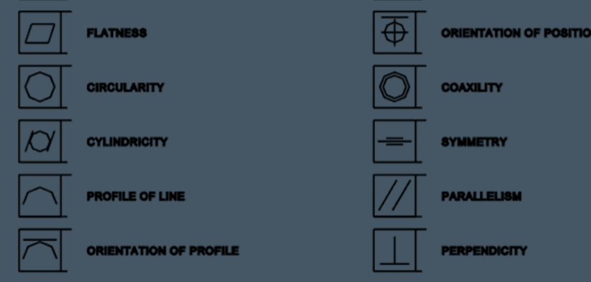
GD&T tolerances are an aspect of Geometric Dimensioning and Tolerancing (GD&T), a system of communicating how a part is to be produced. Typically, a series of 14 standard symbols are used to help guide the people who are making a part.
Along with the GD&T symbols, GD&T tolerances are included in an engineering drawing to provides insight into positioning, cylindricity, and other characteristics that are vital to the part’s manufacturing and, ultimately, its functionality.
GD&T tolerances must balance functionality and cost.
When the drawing for a part is conceived, it is engineered to perfection — the ideal of how the part should be. However, in an imperfect world, it is not realistic to think that every part will be 100% perfect every time. Therefore, allowable tolerances are incorporated into the engineering process — allowing for acceptable imperfections while ensuring that the parts will be fully functional.
GD&T tolerances communicate the allowable tolerances that are associated with the part. The tighter a tolerance is, the more difficult it will be to achieve, the greater the number of rejections, and the higher the cost. Therefore, it is important to specify an allowable tolerance that is tight enough to make the part functional but loose enough that producing the part will still be cost-effective.
A GD&T chart can guide you.
A quick search online for “GD&T” will lead you to a range of resources including examples of GD&T charts. These charts generally show the different symbols that are used, explain what they mean, and describe how to use them.
The GD&T symbols help to describe various characteristics of form, orientation, profile, runout, and location. A drawing will typically show a series of boxes with:
- The appropriate symbol for the location of a part feature (such as its position)
- The shape of the feature (such as a circle for a hole)
- The total allowed tolerance
- Feature modifiers (such as maximum material condition)
- Any required additional datum
One of the symbols used most commonly with GD&T tolerances is true positioning, which is represented by a circle with a cross through it. A typical example is bolt holes in a piece of steel, where each hole must be positioned so that the bolts align and fit properly. As you might imagine, positioning most often deals with mated parts that need to work together — as in the above example, where holes need to be placed correctly in order that bolts will match up with a corresponding steel part.
Where are GD&T tolerances used?
At Metal Cutting Corporation, we cut thousands of rods, tubes, and wires every day. While tolerances are of course involved, we are not typically producing parts that require specified positioning. However, some GD&T tolerances are necessary for complex parts that we produce on our swiss-type automatic lathe, as well as certain parts produced on our CNC lathes and mills.
In addition, we often deal with an end radius that ultimately needs to fit somewhere else. For instance, we might produce a small pin that our customer will mate with a corresponding part. In these cases, we need to ensure that the pin is the correct diameter AND also that the end radius is not too sharp and there are no burrs that will prevent the pin from mating with the corresponding part. If the GD&T tolerances of either part are off by too much, the parts won’t marry.
How do GD&T tolerances add up?
When working with GD&T tolerances, it is important to remember that all tolerances need to be taken into consideration. For example, if you have a positional tolerance of ± 0.0010 for two parts that must fit together, the cumulative tolerancing means that each part can only be ± 0.0005. This is known as tolerance stacking.
Generally, we rely on our customers and their designers and engineers to determine the correct GD&T tolerances for their parts. However, sometimes we come across specs that just don’t add up. At these times, we need to know the right questions to ask to keep the project on track.
For example, a customer might specify a part that will undergo multiple processes, but have a total tolerance that is smaller than the cumulative tolerances when you add up each step (process) of production. Here, we need to find out what feature is most important to the part’s functionality, so that it can have the tightest tolerance and the others features’ GD&T tolerances can be loosened to achieve the specified total tolerance.
Take the example of a medical device that needs to fit and lock in place with another part. Is the stepped area most critical to the part fitting together and locking, to achieve the desired functionality? Or is the length of the device more important?
Bring it all together.
It is also important to consider how a part is being made and the tools that will be used. For instance, a customer may ask us to grind a part to achieve a particular feature but be unaware that a grinding wheel is not perfectly square and will create a corner radius. Here, we would need to ask the customer if a corner radius matters to functionality — and if so, how big a radius would be acceptable and how tight the tolerance needs to be.
It is easy to see that GD&T tolerances can be critical to how parts fit and work together, which is ultimately a key to achieving the desired functionality as well as cost-effectiveness.


