Achieving Tight Tolerances for Roundness Requirements
Specifying tolerances for the mission-critical features of a part is a crucial element of optimizing for manufacturability.
When customers come to Metal Cutting Corporation with a request for a certain circularity tolerance on the small metal parts we fabricate for them, it opens up some interesting questions.
What is circularity? And how do you determine whether a part meets the criteria that allow it to be described as “circular”?
Multiple ways to define circularity
In the simplest terms, circularity is a description of roundness, or how closely an object resembles a true circle.
In our world, circularity is a two-dimensional measurement of how round an object is at one point along a cylinder. Circularity tolerance is specified to control the form of that circular object to ensure that it’s not too oblong, square, or out of round.
Circularity tolerance is concerned with only one point on the part, not its relationship to anything else or the entire length of the cylinder. This is unlike concentricity, which compares roundness at two different points, and cylindricity, which is a three-dimensional look at both roundness and straightness along the axis of a part. (Read more about circularity, concentricity, cylindricity, and other related terms.)
ID vs. OD for circularity tolerance
When specifying circularity tolerance, it is important to be clear what you want to be measured — for instance, are you talking about the inside diameter (ID) or the outside diameter (OD)? — and which point along the cylinder is most important.
For example, when tumbling parts (such as pins) for radius, we know that the diameters at the ends will be slightly different than the diameter at the middle. The larger the radius, the farther in from the ends the diameter will be affected.
Therefore, we typically measure circularity at the middle of the part. However, with a tube, the ID can only be measured at the ends.
At Metal Cutting, we generally work with rods and tubes — true round objects that have the same diameter throughout the part. (If the diameter was not the same throughout, the object would be oval rather than round.)
Whether we are working with a tube or a solid, we focus on the OD to determine the circularity tolerance. Here, measuring the diameter at several points around the part gives you a good idea of whether the part is truly circular.
Is a round figure with flat sides “circular”?
Although the broad definition of circularity can also describe shapes such as hexagons and other figures with flat sides, in general the parts we measure are, indeed, round.
However, we do grind and cut polygonal parts to length, including square or rectangular sides and even complex polygons. In these cases, different measuring techniques are used to determine whether the parts are within customer specifications for circularity tolerance.
Illustrating circularity
In Geometric Dimensioning and Tolerancing (GD&T), the symbol used to show circularity in engineering drawings is — as you would expect — a circle. Typically, the drawing will have a callout box pointing to the corresponding part surface, with the callout containing a circle and the appropriate circularity tolerance.
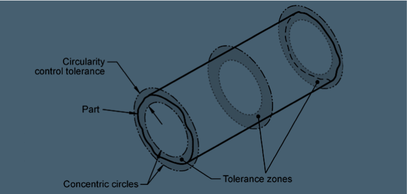
Another way to show GD&T circularity is to draw the part’s tolerance zone — two concentric circles that differ in diameter by the part’s specified tolerance.
The two concentric circles show the maximum and minimum sizes between which all points of the specified part’s diameter must fit for it to be deemed sufficiently round and within the required circularity tolerance.
In other words, the part must fit inside the tolerance zone between the inner and outer circles. (Amazingly, this can be true even for hexagons, stars, and other flat-sided shapes, allowing them to be considered to have a circularity tolerance.)
Specifying circularity tolerance
If you search for GD&T circularity examples, you’ll likely find drawings of shapes with tolerances such as ±0.050” (1.270 mm) or ±0.030” (0.762 mm). Here at Metal Cutting, where we specialize in very small, precise parts, 0.050” or 0.030” out of round is huge!
More often, we deal with circularity tolerances such as ±0.001” (0.0254 mm), ±0.002” (0.0508 mm), or even as close as ±0.0002” (0.0051 mm). In fact, there are customers for whom circularity is measured in millionths of an inch.
Specifying where to measure for circularity
Working with such tiny parts, when customers ask for a circularity tolerance, they typically ask us to look at the diameter around the part at a particular point — usually the OD and most often, at the middle of the part — to determine if the part meets their specifications.
Granted, uniform diameter is not a perfect definition of what circularity is. However, most of our customers find it meets their requirements for controlling roundness and helping to ensure that parts fit properly, move smoothly, and wear evenly.
Where customers request it, special devices can be used to measure true circularity rather than diameter. For example, there are probes that are capable of measuring all the way around a part.
Whatever tolerance, inspection method, and measuring device is appropriate for circularity or any other critical feature of a part, including those details (and more) in the request for quote will help to ensure that the part is optimized for manufacturability.


